


1830 AIR HOE DRILL
Air Hoe Drill
- Positive depth control features and options
- Choice of ground-engaging openers
- Longer machine life with flexible frame
- Remote height sensors
Features
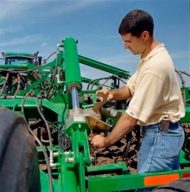
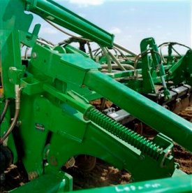
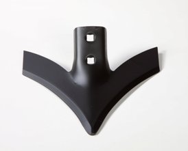
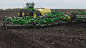 Side-to-side flexibility demonstrated by 1830
Most producers view purchasing a seeding system as a long-term investment. The life requirement of these robust machines is four times longer than previous models. That is why the John Deere seeding group has built even more durability into the 1830 and 1835 Air Hoe Drills.
An advanced and rigorous testing program has proven the machine durability to the extent that John Deere now offers a three-year frame warranty with each 1830 and 1835 that rolls out of the factory.
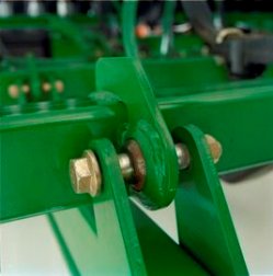 Robust ball joints
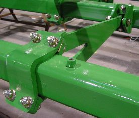 Cast rank tube connectors
Robust ball joints connect strong fore-aft tubes to 100-mm x 100-mm (4-in. x 4-in.) rank tubes, which are joined to one another by pivoting rank connectors. Both the mainframe and wing sections share this durable construction that enables the frame to flex diagonally, relieving stress on solid frame members and avoiding frame failures.
Seed smart with confidence that the 1830 and 1835 will endure the field conditions.
Seed depth uniformity
 Diagonal frame flexibility keeps openers engaged
Producers are more attuned to the importance of seed depth than ever before. A uniform-looking field is not the only goal; yield is too. Proven yield penalties across the world range from 5 percent to 25 percent, depending on depth variance.
The 1830 and 1835 feature diagonal mainframes and wing flexing – helping openers maintain their depth over uneven terrain.
Setting depth is one of the most critical adjustments an operator will make to a seeding tool. John Deere understands every operator needs dependable, repeatable depth control that is easily adjustable. Not every producer agrees on how to make it. That is why John Deere provides a choice of two depth control options on the 1830 and 1835.
Mechanical depth shims are repeatable and reliable
 Adjusting mechanical depth shims
Often-heard are comments from producers who say they prefer the positive mechanical depth control offered by the 1820. This popular concept is base equipment on the 1830 and 1835 air hoe drills.
Two indexed depth shim packs on the mainframe are not only easy to set, but reduce the number of adjustment sites over previous designs by up to 60 percent.
Less time adjusting means more time seeding.
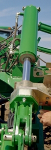
TouchSet™ depth control
Changing field conditions such as moisture levels and soil types can make setting depth a challenge. TouchSet depth control makes adjusting depth in response to changing field conditions easy and profitable. On 8R and 9R Series tractors, the operator uses selective control valve (SCV) #1 and the SCV TouchSet control panel to perform all the depth control functions from the seat. Considering yield penalties of 5 percent due to seeding 2.5 cm (1 in.) too deep or too shallow, the convenience of in-cab adjustment pays nicely.
NOTE: Repeatability is +/- 6 mm (0.25 in.) to preset depth. If your seeding operation requires accuracy greater than +/- 6 mm (0.25 in.), the use of shim packs is recommended.
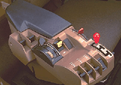 Control arm
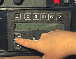 CommandCenter™
How does it work? The operator uses the TouchSet (SCV setup panel) to set or change the operator depth.
- With the implement nine-pin connector connected to the tractor, start the tractor; a P will appear in the window of the control panel under SCV #1.
- The remote sensor located on the rockshaft monitors position of the implement.
- After operating depth is measured at the ground engaging tool and the desired depth obtained, press the lower set button on the control panel. That depth is now set.
- On-the-go depth changes can be made by touching the set button to select a new depth.
- Implement raise height selection uses the upper set button on the control panel to preset the distance the implement is raised above the operating depth.
Preset the raise height to:
- Take out wheel tracks on headlands
- Limit raise height for waterway crossings
- Manual depth override capacity
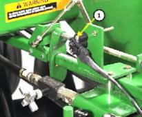 Remote position sensor
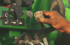 Electrical connector
A remote position sensor (1) is located at the rear of the drill; electronically monitors the positions of the implement.
An electrical connector is used for easy hookup of TouchSet depth control sensor on the implement to the tractor system (8R Tractor illustrated).
NOTES:
- For use with all 8R and 9R (or older models) Series John Deere tractors.
- TouchSet depth control requires additional tractor parts for hookup; see appropriate tractor section in this Sales Manual.
1830
Code | Bundle | Description |
2500 |
| Positive mechanical depth control |
2505 |
| TouchSet depth control plus positive mechanical depth control |
1835
Code | Bundle | Description |
2510 |
| Positive mechanical depth control with active hydraulic down-pressure system for separate fertilizer placement (SFP) |
2515 |
| TouchSet depth control and positive mechanical depth control with active hydraulic down-pressure system for SFP |
The correct tires are critical to the overall performance and productivity of an air hoe drill. The John Deere Seeding Group recognizes the wide variance in conditions and tire needs around the world. Five tire options are provided for the 1830 Air Hoe Drill.
To select the appropriate tire, consider the discussions and matrixes below.
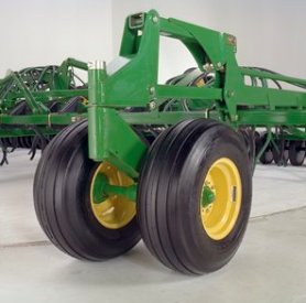
Wheels in base equipment on 1830 mainframe are:
- Dual front caster wheels
- Dual rear transport wheels
Equip the wing sections with duals in the following situations:
- Maximum flotation is required for wetter soils or conditions
- No requirement to have openers seeding outboard the outer wing caster tire
- Rough field conditions that could lead to potentially inconsistent seed depth
12.5L-15 tires - base equipment for 1830
 12.5L-15 tire
The 12.5L-15 tire (code 2210 or 2215) brings load-carrying capacity and puncture resistance.
For additional capabilities in the following situations, consider optioning up to high-flotation, wide-profile knobby tire option (code 2220):
- Transporting on soft, rural roads
- Operating in generally wetter, softer field conditions
- Additional puncture resistance is required
33x15.5-16.5 and 31x13.5-15 high-flotation tires
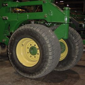 33x15.5-16.5 tire
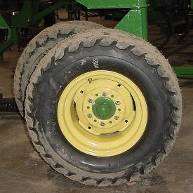 31x13.5-15 tire
The high-flotation tires (code 2220) provide the best performance in all categories with the exception of tire overlap (pass-to-pass) and replacement tire considerations. The size of the machine will depict whether the mainframe will receive 33x15.5-16.5 or 31x13.5-15 size tires (see matrix below).
Tire selection by base code and option code
What tires are included with each base code and option code? This can be a complicated question and present unwarranted confusion. Each machine configuration is equipped with the tire that is meets the minimum load carrying capacities required of the machine size. Below is a chart that describes the tire that accompanies each code.
Code |
| 2210 | 2215 | 2220 |
Wing configuration |
| Single | Dual | Dual |
Model/size | ||||
1830-34 | Mainframe duals | 12.5L15 FI LR D | 12.5L15 FI LR D | 31x13.5-15 10 PR |
| Wing | 12.5L15 FI LR D | 12.5L15 FI LR D | 31x13.5-15 10 PR |
1830-41 | Mainframe duals | 12.5L15 FI LR D | 12.5L15 FI LR D | 31x13.5-15 10 PR |
| Wing | 12.5L15 FI LR D | 12.5L15 FI LR D | 31x13.5-15 10 PR |
1830-50 | Mainframe duals | 12.5L15 FI LR D | 12.5L15 FI LR D | 33x15.5-16.5 10 PR |
| Wing | 12.5L15 FI LR D | 12.5L15 FI LR D | 31x13.5-15 10 PR |
1830-61 (18.60 ) | Mainframe duals | 12.5L15 FI LR F | 12.5L15 FI LR F | 33x15.5-16.5 10 PR |
| Wing | 12.5L15 FI LR D | 12.5L15 FI LR D | 31x13.5-15 10 PR |
1835-41,50 (12.50 & 15.20 m | Mainframe duals | 12.5L15 FI LR D | 12.5L15 FI LR D | 33x15.5-16.5 10 PR |
| Wing | 12.5L15 FI LR D | 12.5L15 FI LR D | 31x13.5-15 10PR |
1835-61 | Mainframe duals | 12.5L15 FI LR F | 12.5L15 FI LR F | 33x15.5-16.5 10 PR |
| Wing | 12.5L15 FI LR D | 12.5L15 FI LR D | 31x13.5-15 10 PR |
To determine which code is most appropriate for a given situation, see the chart below, which outlines some considerations for tire package selection.
Tire code suitability by application
Code |
| 2210 | 2215 | 2220 |
Wing configuration |
| Single | Dual | Dual |
Selection criteria | Application | |||
Load rating | Extensive road transport or heavy options | Best | Best | Better |
Flotation - Road transport | Transport on soft rural roads | Good | Good | Best |
Flotation - Field edges | Operation around field wet spots | Good | Better | Best |
Puncture and stubble resistance | Road and field hazards or tough stubble | Better | Better | Best |
Wing operation stability | Operation in rough fields | Good | Best | Best |
Overlap with previous pass | Operation without guidance systems | Best | Better | Good |
Availability of replacement tires | Operation far from retail centers | Better | Better | Good |
Cost of replacement tires |
| Better | Better | Good |
Transporting large machines on public roads can be a little stressful. Passing motorists, mailboxes, overhead lines, and trees can all contribute to potential hazards.
With so much to focus on, the 1830 Air Hoe Drill operator should not have to worry about openers engaging the pavement when lowering a machine to clear an overhead obstacle.
With the optional transport height reduction feature, the operator does not need to worry. This handy feature can also serve to set the height for storage inside.
How it works
 Transport height reduction assembly
Simply setting the pin in the appropriate hole will stop the machine from lowering when the openers are a safe distance above the pavement.
The operator can focus on the overhead obstacle and other hazards such as passing motorists near the machine. This can prevent a potentially damaging encounter with the road surface or even an accident.
The 1830 and 1835 feature a simplified hydraulic system due to a common rockshaft design in the lift circuit. Not only does this tie all sections together ensuring consistent depth from mainframe to wing, it also eliminates 50 percent to 67 percent of the hydraulic cylinders, reducing the chance of hydraulic failure.
 Frame lift cylinder
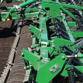 Common rockshaft design
- No rephasing of hydraulic cylinders
- Fewer hydraulic components and hoses to maintain
- Seed with confidence that all air hoe drill sections are seeding at the same depth
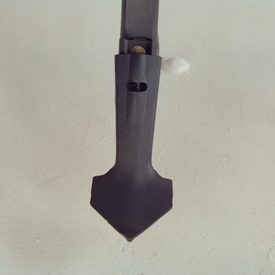
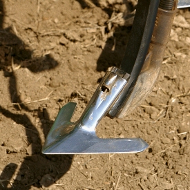
Knife bodies and points
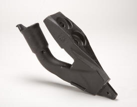 Knife body
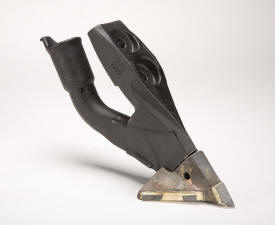 Knife body with 10.2 cm (4 in.) point
Many producers enjoy the moisture-saving benefits of low-disturbance seeding. To make it easier for them to reap the rewards of low-disturbance seeding, factory-installed knife bodies are available for 1830 and 1835 Drills.
The knife bodies are available in 2.5 cm (1 in.) or 10.2 cm (4 in.) spread points.
Use the 2.5-cm (1-in.) point for low disturbance or, if a wider spread pattern is desired to increase seedbed utilization, use the 10.2-cm (4-in.) point. The points can be quickly changed with a single roll-pin fastening system and feature carbide tips to ensure long life.
The knife bodies also feature a positive hose retention system with provisions for a hose clamp to hold the hose in place.
These knife bodies may not perform as designed in wet, sticky soil conditions.
NOTE: Points and roll pins are not included. Points and roll pins are available through Service Parts.
Perma-Loc™ spoons and sweeps
Perma-Loc spoons and sweeps from John Deere offer reduced maintenance because the Perma-Loc design enables a change-out up to five times faster than traditional bolt-on components.
They also offer cost savings because with Perma-Loc spoons and sweeps, there is no more purchasing hardware each time spoons are changed out. This can save $309 USD list price when changing out the spoons on a 18.3-m (60-ft) tool with 19-cm (7.5-in.) spacing.
Save time and money and seed smart with John Deere Perma-Loc spoons or sweeps.
 10.2-cm (4-in.) Perma-Loc spoon
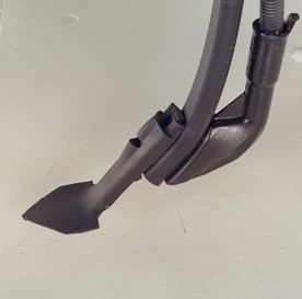 10.2-cm (4-in.) Perma-Loc spoon
Shown is the 10.2-cm (4-in.) Perma-Loc spoon; 7.6-cm (3-in.) spoons are also available.
Spoons are not included in base price and must be ordered separately.
Below is the seedbed profile that can be expected if using a 10.2-cm (4-in.) spoon in conventional tillage with the 1835 Separate Fertilizer Placement (SFP).
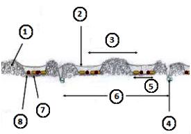 10.2-cm (4-in.) Perma-Loc spoon
- Tilled soil
- Disturbed soil packed over seed row
- 25.4 cm (10 in.)
- Separate fertilizer placement nitrogen
- 10.2 cm (4 in.)
- 50.8 cm (20 in.)
- Seed
- Seed-placed phosphorus
 30.5-cm (12-in.) Perma-Loc sweep and boot
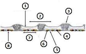 Seedbed profile - 1830 and 30.5-cm (12-in.) Perma-Loc sweeps
- Disturbed soil packed over seed row with 14-cm (5.5-in.) semi-pneumatic packer
- 25.4 cm (10 in.)
- Tilled soil
- Seed-placed phosphorus
- Seed-placed nitrogen
- Seed
- 17.8 cm (7 in.)
- Seed floor created by sweep
Codes for ground-engaging openers
Code | Bundle | Description |
5000 |
| Perma-Loc clip and seed boot for TruPosition™ standard
|
5001 |
| Perma-Loc clip and seed boot for TruPosition openers with sweeps
|
5005 | * | Knife body for TruPosition standard |
5006 |
| Knife body with 2.5-cm (1-in.) tip for TruPosition openers |
5007 |
| Knife body with 10.2-cm (4-in.) tips for TruPosition openers |
5010 | * | Less ground-engaging tools and seed boot for TruPosition and spring-cushion openers |
Perma-Loc removal tool
 Perma-Loc removal tool
This handy Perma-Loc removal tool should be ordered for each drill ordered with Perma-Loc components.
Pinched hydraulic hoses lead to costly downtime. John Deere is aware producers expect machine reliability and a visually pleasing appearance when investing their hard-earned money in a new seeding tool. That is why the John Deere seeding group has placed extra emphasis on securely routing hydraulic hoses on the 1830 and 1835.
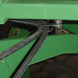 P-clamp
 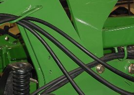 D-ring
All 1830 and 1835 frames are manufactured with weldments to accommodate hose securement sites like the P-clamp and D-ring shown above.
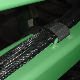 Velcro strap and protective sleeve
Innovative solutions like this Velcro® strap and protective sleeve ensure the reliability of the 1830 and 1835 measure up to John Deere standards. A machine-down repair that takes two hours to fix can mean over 20 ha (49 acres) of lost seeding time.
At a custom rate of $12 per hour, that is at least $600 of lost revenue, or lost yield, if seeding is delayed past mid May (wheat) for many locations.
Velcro is a trademark of Velcro Industries B.V.
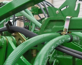
Primary hose routing
 Clamps secure primary air hose
Considerable attention has been given to routing primary seed and fertilizer hose. Reducing sharp bends and eliminating rub points serve to increase hose life and reduce the chance of downtime and skips resulting from holes in the hose.
Additionally, improved clamping and securing methods have been developed specifically for the 1830 and 1835 to maintain hose routing and reduce hose wear.
Hoses are routed at the factory. To expedite dealer setup and ensure proper primary air hose positioning, the 1830 and 1835 incorporate quick couplers at wing and mainframe section joints.
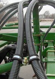
Secondary hose routing
 Clamps secure secondary air hose
Consistent seed and fertilizer delivery to the opener depends on proper secondary air hose routing. John Deere has adopted innovative clamping methods to ensure hoses maintain their shape and stay clear of frame components that could potentially cause premature wear.
 High-productivity bolt-on sweep
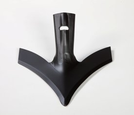 High-productivity Perma-Loc™ sweep
The high-productivity sweep from John Deere was developed to meet current tillage practices and compete in the high-productivity, high working speed market. Thanks to its low profile, curved wing shape, the high-productivity sweep:
- Performs best at a speed of 11.3 km/h to 16.1 km/h (7 mph to 10 mph)
- Easily moves through tougher and higher volume residue
- Retains its shape and width during its wear life
- Wear life is longer than Tru-Width™ sweeps and equal or better than competitors
- Excellent weed control performance
The high-productivity sweeps for the John Deere 1830 Air Hoe Drill comes in 178-mm (7-in.), 229-mm (9-in.), and 254-mm (10-in.), and 305-mm (12-in.) widths, both in the bolt-on and the Perma-Loc version. They fit all 47-degree standards with 44.5-mm (1.75-in.) hole spacing and 11.1-mm (7/16-in.) that currently take Tru-Width sweeps, both John Deere and other makes.
The high-productivity Perma-Loc style sweeps use the current Perma-Loc adapter for 47-degree curved standard N237614. Tru-Width sweeps with the Perma-Loc adapter can seamlessly move the high-productivity sweeps.
The high-productivity sweep also exerts less draft than Tru-Width and major competitors, reducing engine horsepower requirements and diesel consumption.
Specifications
Compare the specifications of up to 4 models
| Key Specs | 1830-air-hoe-drill Current Model |
|---|---|
| Spacing and width #1 | Spacing - 19.05 cm 7.5 in. Width - 12.5 m 41 ft |
| Spacing and width #2 | Spacing - 19.05 cm 7.5 in. Width - 15.2 m 50 ft |
| Spacing and width #3 | Spacing -19.05 cm 7.5 in. Width - 18.6 m 61 ft |
| Spacing and width #4 | Spacing - 25.4 cm 10 in. Width - 12.5 m 41 ft |
| Spacing and width #5 | Spacing - 25.4 cm 10 in. Width - 15.2 m 50 ft |
| Spacing and width #6 | Spacing - 25.4 cm 10 in. Width - 18.6 m 61 ft |
| Spacing and width #7 | Spacing - 31.75 cm 12.5 in. Width - 12.5 m 41 ft |
| Spacing and width #8 | Spacing - 31.75 cm 12.5 in. Width - 15.2 m 50 ft |
| Spacing and width #9 | Spacing - 31.75 cm 12.5 in. Width - 18.6 m 61 ft |
| Spacing and width #10 | |
| Dimensions | |
| Road clearance with sweep | 40.6 cm 16 in. |
| Transport width | 3-section model: 6.2, 12.5 m 20.3, 41 ft 5-section model: 6.2, 15.4, 18.1 m 20.3, 50.5, 59.4 ft |
| Nominal mainframe width (between wing-fold pivots) | 4.19 m 13.75 ft |
| Number of seed openers | Primary air package configurations for the 1830 |
| Spacing and width #1 | Working width 12.4 m 40.625 ft Transport height with harrow 5.86 m 19.22 ft Transport height without harrow 5.57 m 18.28 ft Minimum temporary height reduction with sweeps 457 mm 18 in. Weight With typical options: 11,250 kg 24,800 lb Spacing - 19.05 cm 7.5 in. Width - 12.5 m 41 ft |
| Spacing and width #2 | Working width 15.4 m 50.625 ft Transport height with harrow 4.91 m 16.11 ft Transport height without harrow 4.74 m 15.54 ft Minimum temporary height reduction with sweeps 50.8 cm 20 in. Nominal inner wing width (between wing-fold pivots) 3.08 m 10.1 ft Weight With typical options: 14,900 kg 32,850 lb Spacing - 19.05 cm 7.5 in. Width - 15.2 m 50 ft |
| Spacing and width #3 | Working width 18.1 m 59.375 ft Transport height with harrow 5.53 m 18.13 ft Transport height without harrow 5.49 m 18 ft Minimum temporary height reduction with sweeps 508 mm 20 in. Nominal inner wing width (between wing-fold pivots) 3.82 m 12.55 ft Weight With typical options: 16,330 kg 36,000 lb Spacing -19.05 cm 7.5 in. Width - 18.6 m 61 ft |
| Spacing and width #4 | Working width 12.2 m 40 ft Transport height with harrow 5.86 m 19.22 ft Transport height without harrow 5.57 m 18.28 ft Minimum temporary height reduction with sweeps 457 mm 18 in. Weight With typical options: 10,330 kg 22,775 lb Spacing - 25.4 cm 10 in. Width - 12.5 m 41 ft |
| Spacing and width #5 | Working width 15.2 m 50 ft Transport height with harrow 4.91 m 16.11 ft Transport height without harrow 4.74 m 15.54 ft Minimum temporary height reduction with sweeps 508 mm 20 in. Nominal inner wing width (between wing-fold pivots) 3.08 m 10.1 ft Weight With typical options: 13,540 kg 29,850 lb Spacing - 25.4 cm 10 in. Width - 15.2 m 50 ft |
| Spacing and width #6 | Working width 18.8 m 61.67 ft Transport height with harrow 5.98 m 19.62 ft Transport height without harrow 5.49 m 18 ft Minimum temporary height reduction with sweeps 483 mm 19 in. Nominal inner wing width (between wing-fold pivots) 4.14 m 13.59 ft Weight With typical options: 15,343 kg 33,825 lb Spacing - 25.4 cm 10 in. Width - 18.6 m 61 ft |
| Spacing and width #7 | Working width 12.7 m 41.67 ft Transport height with harrow 5.9 m 19.35 ft Transport height without harrow 5.72 m 18.76 ft Minimum temporary height reduction with sweeps 457 mm 18 in. Weight With typical options: 9,639 kg 21,250 lb Spacing - 31.75 cm 12.5 in. Width - 12.5 m 41 ft |
| Spacing and width #8 | Working width 15.2 m 50 ft Transport height with harrow 4.91 m 16.11 ft Transport height without harrow 4.83 m 15.85 ft Minimum temporary height reduction with sweeps 508 mm 20 in. Nominal inner wing width (between wing-fold pivots) 3.08 m 10.1 ft Weight With typical options: 12,451 kg 27,450 lb Spacing - 31.75 cm 12.5 in. Width - 15.2 m 50 ft |
| Spacing and width #9 | Working width 19 m 62.5 ft Transport height with harrow 6.19 m 20.31 ft Transport height without harrow 6.03 m 19.79 ft Minimum temporary height reduction with sweeps 483 mm 19 in. Nominal inner wing width (between wing-fold pivots) 4.14 m 13.59 ft Weight With typical options: 14,322 kg 31,575 lb Spacing - 31.75 cm 12.5 in. Width - 18.6 m 61 ft |
| Spacing and width #10 | |
| Spacing and width #11 | |
| Spacing and width #12 | |
| Spacing and width #13 | |
| Spacing and width #14 | |
| Spacing and width #15 | |
| Spacing and width #16 | |
| Spacing and width #17 | |
| Spacing and width #18 | |
| Spacing and width #19 | |
| Seed Opener | |
| Type #1 | Spacing 19.05, 25.40, or 31.75 cm 7.5, 10, or 12.5 in. Dimensions 31.75 x 50.8 x 711 mm 1.25 x 2 x 28 in. Trip force 51 degree: 2.45 kN 550 lb-ft Tru-Position™ - 51 degree (angle) |
| Type #2 | |
| Type #3 | |
| Penetration force | |
| Underframe clearance | 71.12 cm 28 in. |
| Fertilizer Opener | |
| Type #1 | |
| Type #2 | |
| Mainframe | |
| Centerframe width | 4.19 m 13.75 ft |
| Cross members | 10.16 x 10.16 cm 4 x 4 in. |
| End tubes | 102 x 102 x 9.5 mm 4 x 4 x 3/8 in. |
| Hitch | Pin: 50.8 mm 2 in. |
| Hitch category | Category 4 |
| Seeding tool depth control | Adjustable mechanical stop |
| Mainframe and wing flexibility | Diagonal flex |
| Fore-Aft Dimensions | |
| Harrow | |
| Press Wheels | |
| Tires | |
| Tractor Hydraulic Requirements | |
| Minimum SCVs | Two |
| Tractor hydraulic circuit requirements | One selective control for frame lift; one selective control for wing fold and transport wheels |
| Tractor hydraulic pressure requirement | 41-ft: 138 bar/min 2000 psi/min 50-ft: 151.7 bar/min 2200 psi/min 61-ft: 172.4 bar/min 2500 psi/min |
| Tractor Horsepower Requirements | |
| 34-ft. | |
| 41-ft. | 205 kW 275 hp |
| 50-ft. | 261 kW 350 hp |
| 56-ft. | |
| 57-ft. | |
| 61-ft. | 317 kW 425 hp |
| 76-ft. | |
| Warning Lights | |
| Freight | |
| Tractor Compatibility | |


© COPYRIGHT 2024 KIBBLE EQUIPMENT - ALL RIGHTS RESERVED| Privacy Policy | Powered By
© COPYRIGHT 2024 KIBBLE EQUIPMENT - ALL RIGHTS RESERVED| Privacy Policy | Powered By