


385A BACKHOE
Backhoe
- Valve spools have machined-metering grooves to allow smooth operation and precise control of several functions
- Improved feel and feathering capabilities
- Strong subframe to ensure the tractor frame can handle the forces created from digging and transporting
Features
Buckets are available in a variety of sizes to fit the job for greater productivity.
- Available in 22.9-cm (9-in.), 30.4-cm (12-in.), 40.6-cm (16-in.), 50.8-cm (20-in.), and 61-cm (24-in.) widths.
- A 45.7-cm (18-in.) heavy-duty bucket is also available.
- All buckets equipped with bolt-on, replaceable, bucket teeth
Double-acting cylinder swing system
The 385A and 485A Backhoes feature twin hydraulic cylinders to control the swing.
- Direct coupling of two double-acting swing cylinders to the swing frame gives precise control
- A very compact swing system
- Simple linkage and chains for easy service
- The large cylinders provide extra torque for backfilling
- The swing system design and subframe mounting allows the backhoe to be close-coupled to the tractor for improved stability
 Flip-over stabilizer pads
Flip-over pads allow a quick and easy conversion between field and street usage.
- Platform is easy to remove for service and to gain access to the valve; the grab handle can be used to lift the entire valve assembly of the backhoe without removing or adjusting control linkages
- Efficient hose routing for better serviceability
- Removal of seat post to access valve requires removal of only one bolt
- Simple design for improved access to hydraulic couplers for attaching and detaching
- Externally mounted boom cylinder provides improved serviceability
- Generous angles of departure; allowing the tractor-mounted backhoe to be loaded onto a trailer more easily, with less need to worry about whether the backhoe bucket will drag the ground as the tractor is driven onto the trailer
 485A Backhoe
The backhoe's mainframe fits into rear mounting brackets installed on the tractor. This provides the following important features:
- Vertical or side-to-side movement is virtually eliminated, providing more stability. The design of the mainframe also positions the entire backhoe close to the tractor. Operators are also able to benefit from the total weight transfer between the backhoe stabilizers and loader bucket.
- The tractor chassis is protected because the mainframe integrates the tractor and backhoe combination together as one.
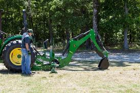
- Once the mounting frame is installed, attaching and detaching is quick and easy.
Installation
- Review the operator’s manual for detailed procedure.
- Back up the tractor to backhoe. Turn off the tractor and engage parking brake.
- Install lift rod to lower draft arms on tractor. Retract drawbar to storage position and remove upper link from tractor three-point.
- Release the parking brake.
- Back tractor into backhoe, engaging lift rod into slots on mainframe. Raise backhoe to full height using the tractor-hitch control lever.
- Turn off the tractor and engage parking brake.
- Secure backhoe to the tractor using L-pins and lynchpins on backhoe.
- Lower the draft arm control lever to relieve pressure in the circuit.
- Connect the hydraulics.
- Make sure the draft arm control lever remains in lowered position.
Removal
- Review the operator’s manual for detailed procedure. Select a firm, level site to remove the backhoe and engage the parking brake.
- Lower boom and install lock pin in park position on backhoe boom.
- Position the backhoe’s bucket so the teeth are parallel to ground.
- Turn off the tractor.
- Disconnect the hydraulics and reconnect the tractor power beyond hydraulics.
- Start the tractor then raise backhoe to full height using tractor-hitch control lever.
- Remove L-pins and lynchpins securing backhoe to tractor.
- Lower backhoe to ground. Make sure lift rod weldment is released from slots in mainframe.
- Release the parking brake and slowly drive the tractor forward so lift rod weldment clears backhoe. Turn off tractor and engage the parking brake.
- Remove lift rod weldment from lower draft arms on tractor. Extend drawbar to operating position and install upper link to tractor three-point.
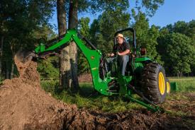
To ensure optimum performance, the tractor's hydraulic flow and increased system pressure are matched with the backhoe's system enhancing the digging force and overall performance.
This backhoe has several features that make it best in class when put on the proper tractors.
Key features include:
- Valve spools have machined-metering grooves to allow smooth operation and precise control of several functions
- Improved feel and feathering capabilities
- Strong subframe to ensure the tractor frame can handle the forces created from digging and transporting
- Buckets are state of the art, designed for optimum productivity; Buckets available in 9-, 12-, 16-, 20-, 24-, and 18- heavy-duty
- Custom thumb allows movement of large and/or uneven shaped objects
- Mid-mount mower compatibility
- 3-point hitch arms can remain on the tractor when backhoe is installed
 Rubber stabilizer pads
Rubber stabilizer pads are available as an attachment. The pads are popular when operating the backhoe on hard surfaces.
- Rubber stabilizer pads keep scratching and damage to ground surfaces minimal
The controls on the backhoe operator console are arranged for optimal comfort, especially important for workdays.
- The controls for the backhoe stabilizers are located on the control tower, which allows easier access to the operator station
- A curved power boom gives the operator a better view of the digging area
- The backhoe features a seat-locking mechanism to keep the seat out of the way when the backhoe is not in use
- Sturdy grab handle on the control tower ensures ease of entering and exiting the tractor
- Backhoe step for mounting/dismounting is located on the cylinder and painted green for easier spotting during enter/exit
- Streamlined control valve and console—no straddling of hydraulic valve with the knees
- Low-mounted valve that allows knee and legroom and keeps heat generated within the valve stack down and away from the operator
- Low noise level due to a low-mounted hydraulic valve
- Two-lever control to operate boom lift, swing dipperstick, and position bucket
- Walk-through operator area for easy enter/exit and maximum comfort
- Direct linkage of control levers to valves provides a better 'feel than cables
- User-friendly controls
- Backhoe seat is adjustable both vertically and horizontally
- Closed boom and dipper give added strength to backhoe
 485A Backhoe
The boom and dipper are designed with the strength to handle the large loads put on these powerful backhoes.
The boom cylinder is run externally on the 385A and 485A Backhoes. This provides better serviceability.
- Adjustable seat pivots up and locks automatically when not in use.
- Low-profile console allows an unobstructed view of the working area.
- Two user-friendly levers are located on the console to control the boom lift, swing, dipperstick, and bucket.
- Updated control linkages require less operator effort and provide a better feel than cables, adding to operator comfort after digging for long hours.
- Grab handle located on control tower and large footrests with non-slip surfaces are provided.
- Swing and boom lock pins for safe transport.
- Backhoe step for mounting and dismounting is painted green for easy spotting during enter/exit.
Specifications
Compare the specifications of up to 4 models
| Key Specs | 385a-backhoe Current Model |
|---|---|
| Digging depth | 103 in. 2.61 m |
| SAE dipperstick digging force | 2449 lb 10893 N |
| SAE bucket digging force | 3752 lb 16689 N |
| Swing arc | 180 degree (angle) |
| Boom lift capacity | 820 lb 372 kg |
| Transport height | 91 in. 2.31 m |
| Stabilizers spread width, up | 62 in. 1.57 m |
| Stabilizers spread width, down | 95 in. 2.41 m |
| Bucket widths | 9 in. (228 mm) 12 in. (305 mm) 16 in. (406 mm) 18 in heavy-duty (457 mm) 20 in. (508 mm) 24 in. (610 mm) |
| Total weight | |
| Backhoe | |
| Swing arc | 180 degree (angle) |
| Bucket rotation | 180 degree (angle) |
| Boom lift capacity | 820 lb 372 kg |
| SAE dipperstick digging force | 2449 lb 10893 N |
| SAE bucket digging force | 3752 lb 16689 N |
| Angle of departure | |
| Hydraulic relief setting | |
| Bucket control main relief valve pressure | 2250 psi 17580 kPa |
| Dimensions | |
| Digging depth | 103 in. 2.61 m |
| Loading height (bucket at 60 degrees) | 78 in. 1.98 m |
| Reach from center line of swing pivot | 140 in. 3.55 m |
| Transport height | 91 in. 2.31 m |
| Loading reach (bucket at 60 degrees) | 51 in. 1.11 m |
| Transport overhang | 48 in. 1.29 m |
| Undercut | 19 in. .48 m |
| Stabilizer type | Stabilizers spread width, up 62 in. 1.57 m Stabilizers spread width, down 95 in. 2.41 m |
| Weight | |
| Total | |
| With RSA side plate kit and 20-in. bucket | |
| With frame adapter and 24-in. bucket | 1390 lb 630 kg |
| With medium frame adapter and 24-in. bucket | |
| With large frame adapter and 24-in. bucket | |
| With 0.4-m (16-in.) bucket | |
| Bucket | |


© COPYRIGHT 2024 KIBBLE EQUIPMENT - ALL RIGHTS RESERVED| Privacy Policy | Powered By
© COPYRIGHT 2024 KIBBLE EQUIPMENT - ALL RIGHTS RESERVED| Privacy Policy | Powered By