


9370R TRACTOR
Tractor
- John Deere PowerTech™ PSS 9.0L
- e18™ PowerShift Transmission
- CommandView™ III cab
- Gen 4 CommandCenter™
- ActiveSeat™ Suspension
Features
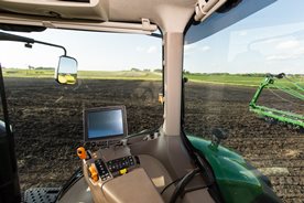
 CommandView III cab
The standard CommandView III cab offers unsurpassed visibility, operator comfort, control placement, and ride and sound quality.
Features:
- ComfortCommand™ seat with air suspension, lumbar support, swivel, fore-aft and lateral attenuation, backrest angle adjustment, adjustable left-hand armrest, and 40-degree right-hand seat swivel
- Operator presence system that warns if the operator is out of the seat while operating key functions
- Folding instructional seat
- CommandARM™ control center with integrated controls
- 4100 or 4600 Generation 4 CommandCenter™ processor
- Behind-the-seat storage
- Left-hand storage compartment
- Passive noise reduction system
- Service ADVISOR™ diagnostic system data port
- Tilt/telescoping steering wheel with position memory
- Swing-out rear window, opens 30 degrees
- Right- and left-outside mirrors (manually adjustable mirror head)
- Monitor mounts on right-hand front post and rear cab post
- Standard radio package, including AM/FM stereo and weatherband with remote controls, auxiliary input jack, four speakers, and an external antenna
- Laminated glass
- Air conditioner and heater with automatic temperature controls (ATC)
- Two 12-V convenience outlet (cigarette lighter style)
- One 12-V 3-pin outlet with adapter (provides switched and unswitched power)
- One International Organization for Standardization (ISO) 9-pin connector
- Power strip with convenience plug adapter
- Hitch control lever lock and selective control lever lock
- Two-speed and intermittent front and rear wiper with washer
- Front pull-down sunshade
- Digital cornerpost display with:
- Fuel level gauge, including low fuel warning
- Temperature gauge
- Diesel exhaust fluid (DEF) gauge, including low DEF warning
- Engine rpm
- Transmission commanded gear or speed
- Vehicle system functions, such as iTEC™ end-row guidance, that are operating
- Inside-mounted rearview mirror
- Beverage holders sized to accommodate various containers
- Interior left-hand dome light
ComfortCommand seat
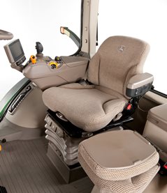 ComfortCommand seat
ComfortCommand seat improves ride quality and helps to reduce operator fatigue
Features include:
- Armrests, lumbar support, and backrest angle are easily adjusted to match operator preference.
- Shock absorbers dampen the motion effect of the tractor for an improved ride.
- Seat height adjustments are conveniently located on the left armrest.
- Fore-aft adjustment is easy to reach located on the left front of the seat.
- Swivel adjustment, located on the front of the seat, allows the seat to be swiveled 40 degrees to the right or eight degrees to the left of the center position.
- Operator presence switch warns if the operator is out of the seat while operating key functions.
- Seat belt retractor.
- Centered cab seat, providing excellent over-shoulder visibility.
- Adjustable shock absorber permitting ride adjustment from soft to firm to match the operator's desired comfort level.
- Removable cushions for easy cleaning.
CommandARM
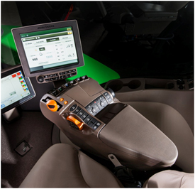
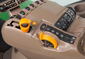 CommandARM controls
John Deere 9 Family Tractors feature the CommandARM with integrated Generation 4 CommandCenter display. The control layout of the CommandARM utilizes a clean and efficient design which groups controls by function and builds upon John Deere’s history of intuitive and ergonomic control placement and operation. The CommandARM’s design allows for a 40 degree right seat swivel and adjustable positioning matching the operator’s preference.
Controls located on the CommandARM include:
- Engine throttle
- Transmission control for e18™ transmission speed PowerShift transmission (PST)
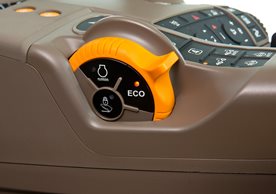
- Eco mode (minimum engine speed) for e18 speed PowerShift transmission (PST)
- FieldCruise™ engine controls
- Selective control valve (SCV) controls
- AutoLoad™ controls (if equipped)
- Differential lock on/off and automatic
- iTEC™ sequence switches
- AutoTrac™ assisted steering system resume switch (if equipped)
- Radio
- Beacon light on/off
- Hazard lights on/off
- Field lights 1/2
- Heating, ventilation, air-conditioning (HVAC) system
Hydraulic controls
Hydraulic controls utilize fingertip paddle pots for raise/lower and extend/retract functions.
 Fingertip paddle pots
Throttle
The throttle design incorporates buttons which control FieldCruise speed, and transmission eco settings.
 Throttle
Tractor function controls
Located just to the right of the throttle is the Auto-Trac activation button and four sequence controls for iTEC functions. Behind the iTEC sequence controls there are buttons which control the activation and deactivation of differential lock. Differential lock can also be activated by the foot switch on the cab floor.
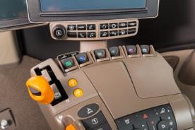
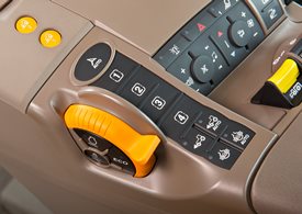 AutoTrac resume and iTEC strip
Controls for radio, lights, rotary beacon (if equipped), hazard flashers, and HVAC system are located to the center-right on the CommandARM, along with power take-off (PTO) for rear PTO.
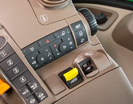 Radio, HVAC, hazard flashers, and PTO controls
Seat swivel
The design of the CommandARM allows for up to 40 degrees of right-hand seat swivel.
 Seat swivel
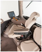 40 degrees seat swivel shown
CommandCenter
 Generation 4 CommandCenter
The Generation 4 CommandCenters feature fast adjustment of tractor functions and controls and are integrated into the CommandARM to create a seamless control center.
The following functions can be adjusted and accessed using the CommandCenter display:
- Hydraulic settings
- Hitch settings
- Transmission settings
- FieldCruise
- iTEC programming functions
- Radio
- Lights
- Add all functionality – diagnostics, display settings, etc.
The Generation 4 CommandCenters have the capability of Remote Display Access (RDA). RDA allows improved communication between an offsite farm manager or dealer and the equipment operator. The user can view exactly what the operator sees on the GreenStar™ 3GS3 2630 Display and Generation 4 CommandCenter from almost any Internet-connected device. RDA is available on the 4600 and 4100 CommandCenter RDA allows for an increase in productivity with quicker problem resolution. By using RDA, the cost of operation will decrease due to reduced labor and travel costs, and maximum efficiency will increase profit.
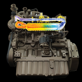 PowerTech PSS 9.0L engine
The John Deere exhaust filter is integrated into the engine design and electronics to provide a seamless operator experience. The engine control unit (ECU) and exhaust temperature management (ETM) system work together to continuously regenerate the exhaust filter using a natural cleaning process sometimes referred to as passive regeneration.
If natural filter cleaning cannot be achieved based on temperature, load, and speed, then particulate matter (PM) must be removed using an automatic cleaning process sometimes referred to as active regeneration. In most cases, filter cleaning does not impact machine operation or require operator involvement. Higher pressures created by our Final Tier 4 (FT4)/Stage IV high-pressure fuel system extend intervals between automatic cleanings.
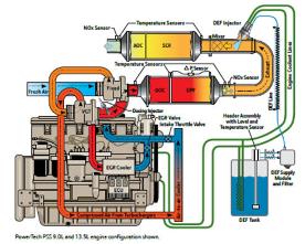
How EGR works
EGR reduces the high temperatures where nitrogen oxide (NOx) compounds are formed in the engine cylinders by replacing excess oxygen with a prescribed amount of cooled exhaust gas.
Exhaust gases contain more carbon dioxide than oxygen. The EGR valve, in conjunction with the venturi and ECU, allows a controlled amount of exhaust gas to enter the intake manifold to mix with the incoming fresh air. Replacing excess oxygen with cooled exhaust gas leads to lower combustion temperatures, creating less NOx. In addition, EGR allows for advanced timing, leading to optimal performance of the engine, maximizing fuel economy.
The following diagrams illustrate how air flows through the engine.
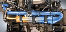
For added performance and efficiency, the engine passes the exhaust gases through an EGR cooler before it enters the engine.
Flow of exhaust during engine operation
Exhaust airflow enters into the EGR cooler from the exhaust manifold near the turbocharger.
Based on engine load, air temperatures, and rpm, the ECU opens or closes the EGR valve, allowing a measured percentage of exhaust gas to enter the intake manifold.
The gases mix with the rest of the incoming air from the turbocharger and aftercooler before entering the cylinders.
The following diagrams illustrate how air flows through the engine (PSS).
For added performance and efficiency, the engine passes the exhaust gases through an EGR cooler before it enters the engine.
 PSS EGR
PSS 9.0L and 13.5L FT4 technology
 PowerTech PSS Final Tier 4 technology
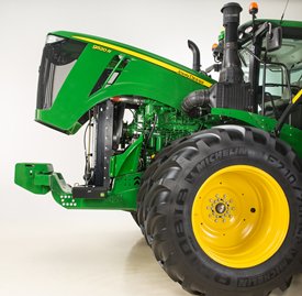 9R, 9RT, and 9RX one-piece hood
Regular service and maintenance are essential to the performance, productivity, and longevity of all farm machinery.
Maximum uptime is an important element of productivity.
- 9 Family service points are quick and simple to check.
- Greater accessibility improves serviceability.
All items in the daily service schedule can be performed without the use of tools:
- Engine oil, hydraulic oil, coolant level, and water separator can be conveniently accessed from ground level without having to open the hood.
- Engine can be easily accessed by simply raising the one-piece hood for more periodic maintenance checks.
- Single-point latch mechanism ensures easy hood opening and closure.
NOTE: Always refer to the operator’s manual for complete maintenance and service recommendations.
Typical maintenance and service information includes:
Refueling
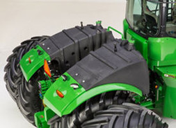 Fuel tank on the 9R
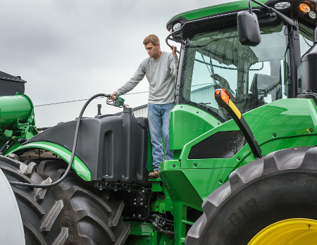 Refueling
The 9R Series Tractors fuel tank is located over the rear axle. The fuel tank features a dual fill design. This design allows the machine to be filled from either side of the fuel tank. A fuel nozzle holder is located on the gudgeon platform when the operator positions themselves on the gudgeon platform to fill the fuel tank.
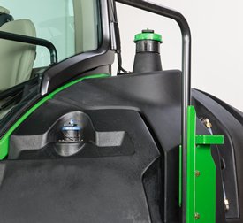
The diesel exhaust fluid (DEF) tank is located on the left-hand side of the tractor indicated by a blue cap. It is fillable from ground level and has a protective shield to keep debris out of the fill neck.
Model | Diesel (gal./L) | DEF (gal./L) |
9370R | 320 gal. (1211 L) | 22 gal. (83 L) |
9420R | 320 gal. (1211 L) | 22 gal. (83 L) |
9470R | 320 gal. (1211 L) | 22 gal. (83 L) |
9520R | 400 gal. (1514 L) | 22 gal. (83 L) |
9570R | 400 gal. (1514 L) | 22 gal. (83 L) |
9620R | 400 gal. (1514 L) | 22 gal. (83 L) |
 Fuel tank on the left side of 9RT
The 9RT fuel tank is located in the same position as the previous 9RT model, on the left-hand main platform.
The 9RT Series Tractors all feature a DEF tank capacity of 22 gal. (83 L). The fill location is near the diesel fill location.
Model | Diesel (gal./L) | DEF (gal./L) |
9470RT | 350 gal. (1324 L) | 22 gal. (83 L) |
9520RT | 350 gal. (1324 L) | 22 gal. (83 L) |
9570RT | 350 gal. (1324 L) | 22 gal. (83 L) |
Model | Diesel (gal./L) | DEF (gal./L) |
9470RX | 400 gal. (1514 L) | 22 gal. (83 L) |
9520RX | 400 gal. (1514 L) | 22 gal. (83 L) |
9570RX | 400 gal. (1514 L) | 22 gal. (83 L) |
9620RX | 400 gal. (1514 L) | 22 gal. (83 L) |
NOTE:
- John Deere supports the usage of bio diesel. Bio diesel should meet ASTM D6751 (US) or EN 14214 (European) fuel quality standards.
- Tractors receive fuel containing a 2 percent bio-diesel blend at the factory
- Acceptable blend levels may vary by geographic region
- Diesel exhaust fluid will freeze when exposed for longer than three hours to conditions below -11°C (12.2° F)
For more information about the use of bio-diesel in John Deere engines, refer to www.JohnDeere.com/biodiesel
Severe-duty water separator, if equipped
The severe-duty water separator can extend service intervals and helps to protect the tractor’s fuel system from damage associated with lower-quality fuel.
Simply open the drain valve on the bottom of the separator and drain-accumulated water.
NOTE: Cummins® QSX 15L engines cannot be equipped with a severe-duty water separator; however, the fuel filter has separating capabilities like the primary filter on John Deere Power System engines.
Engine access
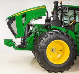 Open hood on 9R
The one-piece tilt hood design provides side shields and guards for additional engine compartment protection. The 9RT and 9RX hoods feature the same design for access to engine components.
Pull out the hood release (located on the front, left side) and tilt hood back to open.
Transmission, hydraulic, and axle oil level
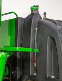
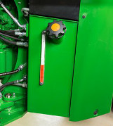 Sight gauge on 9R and 9RX
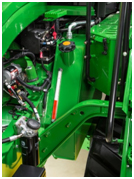 Sight gauge on 9RT
A sight glass for the transmission, hydraulic, and axle oil level is located at the back right side of the gudgeon indicating proper oil levels and an oil fill neck is located on the back right side of the gudgeon for the 9R and 9RX Series Tractor. The oil fill is located on the top of the common reservoir on the left side of the 9RT Series Tractor and a fill tube is located between the steps and engine of the tractor.
- Provides increased filter capacity compared to previous 9R and 9RT Series Tractors
- Transmission, hydraulic, and axle oil should be changed every 1500 hours
- Filter should be changed every 1500 hours unless filter restriction code occurs
- Daily and 10-hour inspections of the transmission hydraulic oil level are recommended
NOTE: The tractor should be off and parked on level ground with the hitch in the lowered position when checking the oil level.
- Sight glass observations will be significantly higher with hot oil temperatures and lower with cold oil or if engine has not run long enough.
NOTE: Oil level above the top mark on the sight glass can result in power loss and heat generation during transport applications.
Primary air filter access
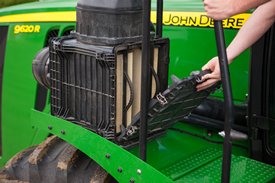 Primary engine air filter inspection
On the 9R and 9RX, the primary engine air filter is accessible from the left-hand platform for replacement annually or as operating conditions require. The filter is aspirated and extends filter life in dusty conditions by aspirating more than 95 percent of incoming dust. Aspirator suction is created by utilizing the air flow from the cooling fan.
On the 9RT, the primary engine air filter is located at ground level on right side of tractor.
Oil change intervals
 Engine oil check/fill location
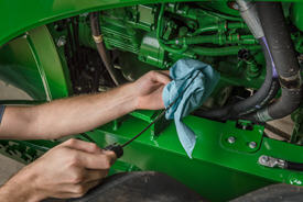 Oil change
Tractors with the 9.0 L and 13.5 L John Deere Power Systems engine features a 500-hour change interval when using approved John Deere Plus-50™ II oil and John Deere oil filter.
Tractors equipped with the Cummins® QSX 15L engine have a 400-hour engine oil and oil filter change interval.
- Previous initial oil and filter change at 100 hours is no longer required due to the factory oil fill of Break-In™ Plus.
- If using anything other than John Deere Plus-50™ II oil, a 250-hour change interval is required. CJ-4 must still be used.
- Only use ultra-low sulfur diesel fuel and CJ-4, ACEA E9, or ACEA E6 oil
- An oil change of 500 hours is possible when using fuel with less than 15 parts per million (ppm) of sulfur, along with John Deere Plus-50 II oil.
See the tractor's operator's manual for oil change intervals and further details.
Cummins is a trademark of Cummins Incorporated.
Battery access
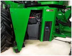 Battery location on 9R and 9RX
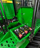 Battery location on 9RT
The 9R and 9RX battery location is behind the left-hand step assembly. There are three bolts that secure the swinging step assembly that need to be removed to completely access the batteries. The 9RT top step of the platform conceals the tractor’s three 12-V batteries 2775 (3-925CCA). Tractors with the Cummins® QSX15 engine will have four 12-V batteries in the same location as tractors equipped with John Deere Power System engines.
Although the batteries are maintenance free, conditions such as long periods of operation at high ambient temperatures and excessive engine cranking may require adding water.
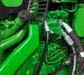
Battery boost terminal
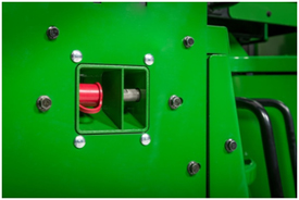 Battery boost terminal
On the 9R and 9RX, a battery boost terminal is located on the left-hand side of the engine for convenient and proper boost assisted starting.
Fuse and relay panel
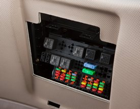 Fuse and relay panel
The electrical fuse and relay panel is located behind the operator’s seat and just below the cab's rear window. Simply lift up on the operator manual cover for access.
- Contains easy-to-replace automotive blade-type fuses and relays for quick servicing.
- Spare fuses are provided for each amperage size used.
The diode module contains many of the diodes contained in the system:
- If a diode problem occurs, simply replace the diode module for easy service and increased uptime.
- Relays are also fully interchangeable for quick service.
Electrical system (smart load center)
The electrical system provides a full CAN-bus based system on the tractor for improved tractor implement integration and flexibility. Incorporated with the system is a smart load center which provides fewer fuses, fewer connectors, and simplified wiring for increased reliability.
The solid-state load center’s primary function is to control the majority of high-current loads, such as fender floodlights and the horn. This electronic circuitry will monitor loads and voltages to provide fast reaction time and the ability to alert the operator if a circuit overloads or if voltage is out of specification, for example open circuit (undercurrent) or short circuit (overcurrent).
Cab air filters
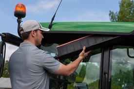 Cab fresh air filter inspection
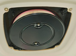 Cab recirculation filter
The cab fresh air filter is conveniently located beneath the left side of the cab for all 9 Family products:
- External service means no mess in the cab from dusty filters
- Filter housing acts as a dust accumulator compartment
- Hand screw eliminates need for tools
- Replace cab fresh air filter every 1000 hours or sooner if plugged or damaged
Cab air recirculation filter
Cab air recirculation filter is located in the roof liner above the operator. 70 percent of the total air volume is recirculated with a blanket effect for enhanced operator comfort.
- Replace cab air recirculation filter every 1000 hours or sooner if plugged or damaged.
Cab air filters are not designed to filter out harmful chemicals. Follow the instructions in the implement operator’s manual and those given by the chemical manufacturer when using agricultural chemicals.
Windshield washer
 Windshield washer bottle on 9R and 9RX
The windshield washer bottle is optional on 9R and 9RX Tractors and is located on the left side of the tractor near the DEF fill point. On 9RT Tractors it is located on the right-side frame.
Maintenance-free U-joint
Maintenance-free U-joint bearings require no servicing to reduce maintenance time.
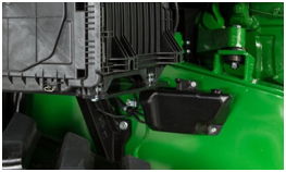
Toolbox
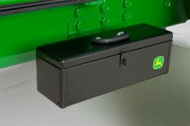 Toolbox for 9R, 9RT and 9RX
A convenient toolbox is located on the left-hand side of the front frame for tool storage and comes standard on all 9R, 9RT, and 9RX Series Tractors.
9R and 9RX Series Tractors have an additional storage box conveniently located on top the left-hand platform.
The 9RT has an additional toolbox is conveniently located next to the left side of the batteries for additional storage.
Cummins is a trademark of Cummins Incorporated.
3-point hitch
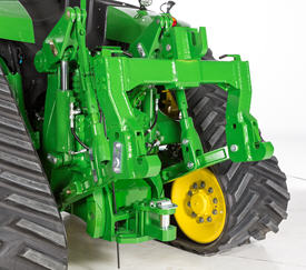 3-point hitch on 9R
The 9 Family Tractors are designed to maximize performance for different applications. The 9R, 9RT, and 9RX Series Tractors offer two different hitch options:
9370R | 9420R | 9470R/9470RT/9470RX | 9520R/9520RT/9520RX | 9570R/9570RT/9570RX | 9620R/9620RX | |
Category 4N/3 with quik-coupler, all axle diameters | Optional – 6804 kg (15,000 lb) | Not available | ||||
Category 4N/3 with quick coupler 120-mm(4.7-in.) axles required | Optional – 9072 kg (20,000 lb) | Not available | ||||
Category 4/4N with quik-coupler, all diameters axles | Optional: 6804 kg (15,000 lb) | |||||
Category 4/4N with quik-coupler, 120-mm (4.7-in.) axle required | Optional: 9072 kg (20,000 lb) | |||||
CommandARM™ controls
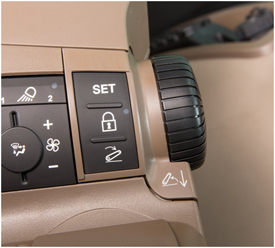 Hitch controls
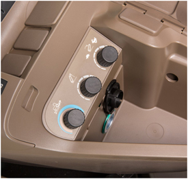 3–point hitch controls under armrest on CommandARM
To help boost productivity, control buttons are located on the 9 Family Tractors CommmandARM to access individual hitch settings. There are three buttons — set, lock, and load depth. There is also a rotary encoder that allows for finite movements of the hitch. The rotary encoder is detented so it clicks for each movement Also, located under the CommandARM are hitch adjustment controls for raise/lower rate.
Hitch load depth
The load depth feature is a useful tool designed to increase performance in tillage applications. Load depth adjustments allow the operator to make adjustments to hitch draft responsiveness.
Draft control helps maintain the operating depth in varying conditions such as rolling terrain and varying soil densities.
An additional feature with load depth control is the hitch slip option. Hitch slip uses wheel slip data to supplement the draft control system. If the wheels slip, the 3-point hitch lifts to allow the tractor wheels to maintain traction with the ground. Once the slip condition is no longer present, the hitch lowers to the required depth as determined by the hitch command and load depth settings.
Both of these hitch command options are easily programmable in the CommandCenter display by pressing the load depth shortcut key, followed by simply using the thumbwheel and confirm key to dial in the desired settings.
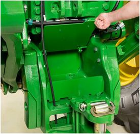
Hitch, external remote control switch
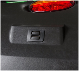 3-point hitch switch on fender of 9R
For added operator convenience, a 3-point hitch remote control switch is located on top of the left rear fender for 9R, 9RT, and 9RX Tractors. The external remote switches enable the operator to raise and lower the 3-point hitch from behind the tractor while hooking to implements.
JDLink, Service ADVISOR, and Service ADVISOR Remote
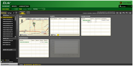 JDLink dashboard
JDLink is the John Deere telematics system designed for operators and managers who desire to take their operations to the next level of productivity and efficiency without leaving the office. Whether it is receiving an e-mail or text message, users can manage the operation in real-time without being in the cab. Using the power of JDLink can optimize productivity, increase uptime, and boost profits with JDLink information all accessible from a laptop, desktop, or mobile device.
JDLink Ultimate provides enhanced machine performance and utilization information that can only be achieved through direct communication with on-board machine controllers. Utilizing John Deere-exclusive telematics technology, users can remotely link to Ultimate-compatible machines to achieve a new level of optimization.
NOTE: Mobile device compatibility and functionality varies.
Monitor assets, performance, and more with JDLink:
- Increase uptime and reduce time spent managing equipment with JDLink Ultimate
- Coordinate machine and labor logistics
- Unleash new possibilities with wireless machine connectivity
- Locate machines on-the-go with the iPhone®, iPad® or Android™ devices JDLink app
- Leverage common components from the JDLink system to enable remote support and machine monitoring
- Industry exclusive Service ADVISOR™ Remote with JDLink
For more information on JDLink activations and subscriptions visit www.StellarSupport.com
NOTE: JDLink is not available in all geographic regions.
Service ADVISOR
 Service ADVISOR
Service ADVISOR diagnostics greatly assist in reducing service costs and downtime. It allows the John Deere service technician to readily extract vital information about tractor malfunctions through the Service ADVISOR data port. Diagnostic codes and CAN bus statistics stored by the tractor and visible in the CommandCenter™ control unit are used by service technicians to isolate, identify, and resolve problems.
Diagnostics and CAN bus statistics are not normally used by the operator. Access and use of trouble codes should only be done by a qualified, factory-trained John Deere service technician.
Service ADVISOR Remote
Service ADVISOR Remote takes the machine connectivity of JDLink and takes it one step further. With Service ADVISOR Remote, machines can be diagnosed remotely, saving the cost of a field service call. For example, diagnostic trouble codes can be reset and software updates can be uploaded remotely.
Apple, iPhone, and iPad are trademarks of Apple Inc. Android is a trademark of Google Inc.
 PTO and shield
Fully independent 1000-rpm PTO is available as a factory- or field-installed option.
- Available on all 9 Family Ag Tractors.
- Full-power capability for maximum utilization*
- 4.45-cm (1-3/4-in.) diameter shaft.
* 9 Family Tractors derate PTO hp when tractor is stationary.
9R – When the PTO is on and ground speed is 0.5km/h (0.31 mph) or less; PTO is limited to 335 hp.
9RT – When the PTO is on and ground speed is 0.5km/h (0.31 mph) or less; PTO is limited to 329 hp.
9RX – When the PTO is on and ground speed is 0.5km/h (0.31 mph) or less; PTO is limited to 335 hp.
See the specs page for model rated PTO horsepower.
The PTO shield has three positions — neutral, up, and down. Use the neutral position when the PTO is connected and ready for use. Use the up position for added clearance when connecting the PTO shaft to the tractor. The down position is used when the PTO is not connected and extra visibility to the drawbar is desired.
Electrohydraulic PTO control
The 9 Family Tractors utilizes an electrohydraulic PTO-engagement switch to activate the optional 1000-rpm PTO.
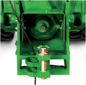
If PTO option is not installed, a storage compartment is located on the rear of the tractor.
 Rear storage compartment on 9R
The e18 transmission delivers smooth shifting and intuitive controls in a reliable 18-speed PST transmission. The e18 transmission with enhanced Efficiency Manager is standard equipment on all 9 Family Tractors.
The e18 has evolved from more than 50 years of John Deere PowerShift technology. With more automatic features, the e18 is easy to operate for all levels of operators and operations. It features three modes of operation, full AUTO, custom, and manual modes. Full AUTO and custom modes manage the engine and transmission to match the desired ground speed to the field conditions. These two modes are ideal for most conditions and take the guess work out of operation. Manual mode is perfect for operators looking to operate the e18 like a traditional PowerShift by bump shifting and managing the engine throttle to their liking.
As the next generation of PowerShift technology, the e18 delivers the strength to handle sudden, high-torque power loads while maintaining responsive, quick, and smooth shifts.
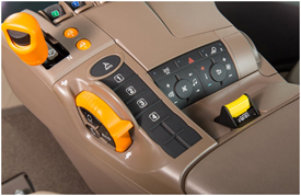
e18 controls
 Shift lever and hand throttle
CommandCenter™ controls
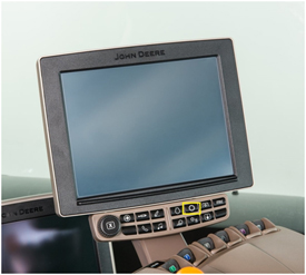
 254-mm (10-in.) Generation 4 CommandCenter
The CommandCenter is the central information system for tractors and allows the operator to program various settings tailored to a specific operation.
To access the tractor’s transmission settings, press the transmission shortcut button on the CommandCenter shortcut bar.
 CommandCenter transmission shortcut button
Operating modes
The e18 application settings employ three modes to take full advantage of the engine-transmission communication: Full AUTO mode, custom mode, and manual mode.
Full AUTO mode
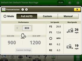 Full AUTO main page
Full AUTO mode manages the tractor’s engine and transmission inputs to reach and maintain the desired ground speed set by the operator. This means the tractor will manage shifts and engine rpm to operate at the most efficient level possible. Operators have the ability to set the maximum forward and reverse speeds for their particular applications. In full AUTO mode the operator can adjust the desired ground speed in two ways, by conducting a traditional bump shift or by rotating the dial on the thumb wheel.
When shifting in full AUTO mode, the transmission shifts set speeds and does not always shift gears, meaning the transmission may not necessarily shift gears if it can reach the desired ground speed with a slightly higher or lower engine rpm. Efficiency Manager is automatically engaged while operating in full AUTO mode. As a result, shifting will not take the tractor out of Efficiency Manager in full AUTO mode.
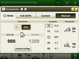
Custom mode
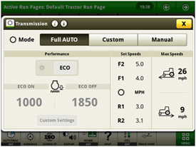 e18 custom transmission page
Custom mode operates similar to full AUTO mode but allows operators to adjust operating parameters to meet a specific operation. It also has the ability to activate eco mode for a higher level of operation.
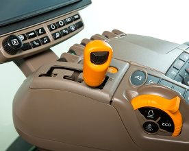
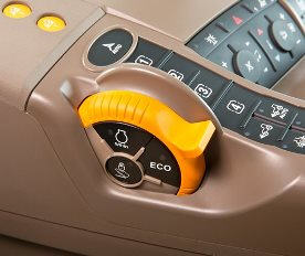 Eco button
 Display screen
Eco allows two minimum engine speeds to be set. Operators can turn eco on and off by either pushing the eco button on the side of the throttle or by selecting eco in the transmission settings page of the CommandCenter controls. For example, operators may choose to turn eco on during transport to utilize a lower minimum engine speed and then turn eco off while operating in the field where a higher minimum engine speed is desired.
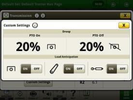 Custom settings page
In the advanced settings page, operators can customize the auto shift engine speed droop as a percentage of the full engine speed. In addition, the load anticipation feature can be enabled for the hitch engagement, hydraulic engagement, or both.
Manual mode
Manual mode operates very similarly to a traditional PowerShift transmission with Efficiency Manager.
In manual mode the operator manages the engine and transmission inputs by controlling the shift lever and hand throttle.
 Manual mode page
Efficiency Manager
 Set speed buttons and set speed adjuster
Efficiency Manager is automatically enabled in auto and custom modes. Efficiency Manager can be turned on in manual mode by selecting the set speed one or set speed two button on the CommandARM™ console. The set speed adjuster on the top of the single-lever gear selector allows the operator to dial in the desired ground speed to establish set speed one or two. Once engaged, Efficiency Manager will manage the engine rpm and gear selection to maintain the desired working speed. To reach the desired set speed, the throttle must be set to full engine rpm.
e18 operation
 e18 operation
Setting start-up gears
The 9 Family Tractors default to 7F and 2R at start up. However, these default start-up gears can be adjusted from 1-13F and 1-3R through the CommandCenter. Refer to the operator’s manual for additional information.
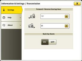 Start-up gears in advanced settings
9R Series Tractor - e18-speed chart for PowerShift transmission (PST) with Efficiency Manager
9R table
Group 47 tires | Group 48 tires | |||
Tire size | (480R46, 20.8R42, 520R42, 620R42, 710R38) | (480R50, 520R46, 620R46, 710R42, 800R38) | ||
Engine (rpm) | 2100 | 2100 | ||
18-speed gear | km/h | mph | km/h | mph |
Forward gears | ||||
F1 | 4.0 | 2.5 | 4.2 | 2.6 |
F2 | 4.8 | 3.0 | 5.0 | 3.1 |
F3 | 5.3 | 3.3 | 5.6 | 3.5 |
F4 | 5.9 | 3.7 | 6.2 | 3.9 |
F5 | 6.5 | 4.0 | 6.8 | 4.3 |
F6 | 7.3 | 4.5 | 7.6 | 4.8 |
F7 | 8.0 | 5.0 | 8.5 | 5.3 |
F8 | 9.0 | 5.6 | 9.5 | 5.9 |
F9 | 9.9 | 6.1 | 10.4 | 6.5 |
F10 | 11.0 | 6.9 | 11.6 | 7.2 |
F11 | 12.2 | 7.6 | 12.9 | 8.0 |
F12 | 13.5 | 8.4 | 14.2 | 8.8 |
F13 | 15.0 | 9.3 | 15.8 | 9.8 |
F14 | 16.6 | 10.3 | 17.5 | 10.9 |
F15 | 20.5 | 12.8 | 21.6 | 13.4 |
F16 | 25.3 | 15.7 | 26.6 | 16.5 |
F17 | 31.2 | 19.4 | 32.9 | 20.4 |
F18 | 38.5 | 23.9 | 40.5 | 25.2 |
Reverse gears | ||||
R1 | 3.9 | 2.4 | 4.1 | 2.5 |
R2 | 5.3 | 3.3 | 5.6 | 3.5 |
R3 | 5.9 | 3.7 | 6.2 | 3.9 |
R4 | 8.0 | 5.0 | 8.5 | 5.3 |
R5 | 9.0 | 5.6 | 9.5 | 5.9 |
R6 | 12.2 | 7.6 | 12.9 | 8.0 |
Group 47 tire based on 710/70R38
Group 48 tire based on 800/80R38
9RT and 9RX Series Tractor - e18-speed chart for PowerShift transmission (PST) with Efficiency Manager
9RT and 9RX table
| 9RT | 9RX | ||
Engine (rpm) | 2100 | 2100 | ||
18-speed gear | km/h | mph | km/h | mph |
Forward gears |
|
|
|
|
F1 | 4.0 | 2.5 | 4.0 | 2.5 |
F2 | 5.0 | 3.1 | 4.9 | 3.0 |
F3 | 5.5 | 3.4 | 5.5 | 3.4 |
F4 | 6.1 | 3.8 | 6.1 | 3.8 |
F5 | 6.8 | 4.2 | 6.7 | 4.2 |
F6 | 7.6 | 4.7 | 7.5 | 4.7 |
F7 | 8.4 | 5.2 | 8.3 | 5.2 |
F8 | 9.3 | 5.8 | 9.2 | 5.7 |
F9 | 10.3 | 6.4 | 10.2 | 6.3 |
F10 | 11.4 | 7.1 | 11.4 | 7.1 |
F11 | 12.6 | 7.8 | 12.6 | 7.8 |
F12 | 14.1 | 8.7 | 14.0 | 8.7 |
F13 | 15.6 | 9.7 | 15.5 | 9.6 |
F14 | 17.3 | 10.7 | 17.2 | 10.3 |
F15 | 21.4 | 13.3 | 21.3 | 13.2 |
F16 | 26.3 | 16.3 | 26.2 | 16.3 |
F17 | 32.3 | 20.1 | 32.2 | 20.0 |
F18 | 39.8 | 24.7 | 39.6 | 24.6 |
Reverse gears |
|
|
|
|
R1 | 4.0 | 2.5 | 4.0 | 2.5 |
R2 | 5.5 | 3.4 | 5.5 | 3.4 |
R3 | 6.1 | 3.3 | 6.1 | 3.8 |
R4 | 7.3 | 3.8 | 8.3 | 5.2 |
R5 | 9.3 | 5.8 | 9.2 | 5.7 |
R6 | 12.6 | 7.8 | 12.6 | 10.3 |
Dual hydraulic pump system
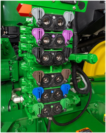 Selective control valve (SCV) stack
Optional high-flow hydraulics are available on 9 Family Tractors by ordering code 3270. The high-flow hydraulic system provides an additional 215 L/ min (57 gpm) of flow for a total of 435 L/ min (115 gpm). This system is ideal for hydraulic fan motor demands. This system is recommended for agricultural implements with continuous flow requirements. When maximum hydraulic pump capacity is reached, multiple functions will continue to operate at the same proportional flow rate.
The 9 Family Ag High-Flow Tractors have two parallel hydraulic systems. The benefit of this system is that functions can be split between the two systems. Functions that require high flow and low pressure can be combined on one system (for example, air seeder fans, and planter motors). Functions that require high pressure and low-flow can be connected to the remaining system (for example, implement lift, fold, and constant down-pressure systems).
Following these guidelines allows the hydraulic system to run cooler as it prevents both hydraulic pumps from running at high pressure. In general, pumps forced to run at both high pressure and high flows generate much more heat than a pump running at a lower flow or lower pressure.
The system operates with two hydraulic pumps:
- Pump 1 - provides hydraulic flow of up to 215 L/min (58 gpm) to SCVs 1, 2, and 3. These SCVs are useful for operating lift/lower and other cylinder type hydraulic needs.
- Pump 2 - attaches in front of pump 1 and provides hydraulic flow of up to 215 L/min (57 gpm) to SCVs 4, 5, and 6. These SCVs are useful for operating hydraulic motors to drive air/fan or vacuum systems on seeding/planting equipment.
- All SCV oil returns to one common hydraulic reservoir.
Specifications
| Official Test | 9370r-tractor Current Model |
|---|---|
| Engine | |
| Manufacturer | John Deere |
| Engine family | PowerTech? PSS 9.0L |
| Aspiration | Dual Series Turbocharger w/fixed geometry first stage-variable geometry second stage - air-to-air aftercooling and cooled exhaust gas recirculation |
| Cylinders/Displacement, cu. in. (L) | 9.0 L 548 cu in. |
| Cylinder Liners | Wet-sleeve |
| Fuel tank capacity, US Gal. (L) (Open; Cab) | Standard 1173 L 310 U.S. gal. |
| Underhood muffler | |
| Performance | |
| Advertised PTO hp (kW) @ Rated rpm | 250 kW 335 hp |
| Official PTO hp (kW) @ Rated rpm | |
| Advertised Engine hp (kW) @ Rated speed | 272 kW 370 hp |
| Max Unballast Drwbr hp (kW) @ Eng rpm | |
| Maximum Torque (PTO) @ rpm, lb-ft (Nm) | |
| Max Torque Rise (80% rtd spd) @ Eng rpm | 38 percent |
| Maximum Torque Rise % (PTO) @ Eng rpm | |
| Fuel Use, U.S. gal./hr & hp hr/gal. at: | |
| PTO @ Rated Eng rpm | |
| Standard PTO Speed @ Eng speed | |
| Maximum PTO Power @ Eng rpm | |
| Maximum Engine Power @ Eng rpm | |
| Max Unballasted Drawbar Power @ Eng rpm | |
| 75% Load, Full Engine rpm (Unballasted) | |
| 75% Load @ Reduced rpm (Unballasted) | |
| Transmission | |
| Std. Transmission; Forward/Reverse | e18? 18-speed PowerShift 40 kph (25 mph); 18F, 6R with Efficiency Manager? |
| Opt. Transmission; Forward/Reverse | |
| Reverser | No |
| On-the-Go Shifting (Yes/No/Partial) | Yes |
| Clutch; Wet/Dry | |
| Creeper | |
| Power Take-Off (PTO) | |
| Standard | |
| Optional | 45 mm 1.75 in. 20-spline 1000 rpm |
| PTO Speeds @ Engine rpm | |
| PTO Actuation | Electronic |
| Hydraulics | |
| Type | Closed-center, pressure/flow compensated |
| Pump Rated Output, GPM (L/min.) | Standard 220 L/min 58 gpmOptional 435 L/min 115 gpm |
| Rated Flow @ One SCV, GPM (L/min.) | Standard coupler: 132 L/min 35 gpm 12.7 mm 0.5 in. Optional coupler: 159 L/min 42 gpm 19.0 mm 0.75 in. |
| Max Output @ SCV Couplers, GPM (L/min.) | |
| Maximum Operating Pressure, psi (kPa) | 20,000 kPa 2900 psi |
| Maximum Hydraulic Power, hp (kW) | |
| Hitch Draft Control Load Sense Type | Electrohydraulic |
| Remote Control Valves Available | 4 - 6 factory, up to 8 field installed |
| Hitch Category (SAE Designation) | 4N/Cat. 3, 4N/Cat. 4 |
| Hitch Lift Cap. lb (kg) @24 in. Bhnd Lift Pt. | Standard 6804 kg 15,000 lbOptional 9072 kg 20,000 lb 6804 kg 15,000 lb |
| Hitch Lift Cap. lb (kg) @24 in. Bhnd Lift Pt. (SAE) | |
| Hitch Lift Cap. lb (kg) @24 in. Bhnd Lift Pt. (ASAE) | |
| Sensing type | Electrohydraulic |
| Joystick SCV control | |
| Final Drive | |
| Type | Inboard planetary |
| Differential controls | Full-locking electrohydraulic |
| Availability | Front & Rear Standard |
| Engage On-the-Go Rear Differential Lock | Yes |
| Axle Type | Single reduction |
| Brakes, Type and Control | Hydraulic power, wet disk, self adjusting on front and rear axle |
| Operator Station | |
| Rollover Protective Structure, OOS | |
| Cab | Doors One - left handSeat Suspension System Standard: Air Optional: Active Seat™ |
| 2WD Dimensions | |
| Wheelbase, in. (mm) | |
| Front Tread Range, in. (mm) | |
| Rear Tread Range, in. (mm) | |
| Minimum Rear Tread Setting, in. (mm) | |
| Front Axle Clearance, in. (mm) | |
| Turning Radius w/Brakes, ft (m) | |
| Turning Radius w/o Brakes, ft (m) | |
| Unballasted Operating Weight, lb (kg) | |
| Approx. Ship Wgt, lb (kg) Open; Cab | |
| MFWD Dimensions | |
| Wheelbase, in. (mm) | |
| Front Tread Range, in. (mm) | |
| Front Axle Clearance, in. (mm) | |
| Turning Radius w/Brakes, ft (m) | |
| Turning Radius w/o Brakes, ft (m) | |
| Limited Slip Differential | |
| Unballasted Operating Weight, lb (kg) | |
| Approx. Ship Wgt, lb (kg) Open; Cab | |
| 4WD Dimensions | |
| Wheelbase, in. (mm) | 3807 mm 149.9 in. |
| Wheel Tread, Min. to Max. in. (mm) | |
| Turning Radius w/o Brakes, ft (m) | 5.55 - Group 47 Tires m 18.2 - Group 47 Tires ft 5.88 - Group 48 Tires m 19.3 - Group 48 Tires ft |
| Nebraska Test Unballasted w/Duals, lb (kg) | |
| Unballasted Weight, lb (kg) | |
| Standard Tires | |
| 2WD | |
| MFWD | |
| 4WD | 620/70R46 in. 167A8 R1W radial in dual wheel configuration |
| Track widths | |
| Miscellaneous | |
| Country of Manufacture | Waterloo, Iowa, USA |
| Ballasting Restrictions, lb (kg) | Lesser of 22,105 kg 48,700 lb or Tire Capacity |
| *Notes |


© COPYRIGHT 2024 KIBBLE EQUIPMENT - ALL RIGHTS RESERVED| Privacy Policy | Powered By
© COPYRIGHT 2024 KIBBLE EQUIPMENT - ALL RIGHTS RESERVED| Privacy Policy | Powered By